Top Product Innovations C6 & C10 Installation Instructions
This step – by – step installation guide is designed and structured to provide you with important information that is required to successfully install the C6 or C10 Phenomenal Aire product. The layout of the guide is structured in a specific order – starting with an overview video directly to the right of this text, a detailed list of tools required to install the product, a step – by – step installation guide and frequently asked installation questions.
Also, we provide contact information at the top of the guide and a link to register the product once installed.
Call With Questions:
(888) 505-2988
Recommended Installation Tools
We recommend using these tools for installing the Phenomenal Aire System.

Wire Stripper

Wire Cutter
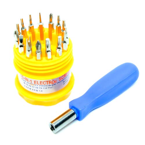
Screwdriver – Straight Bit #2 & Phillips Bit #2

Lock – Out Tag
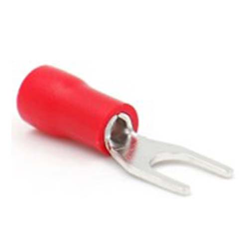
Red Crimp
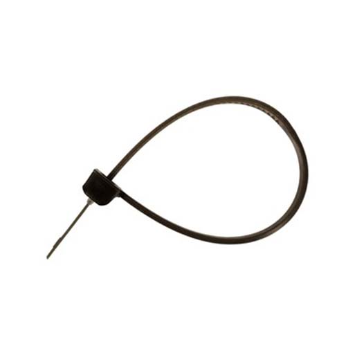
Wire Tie
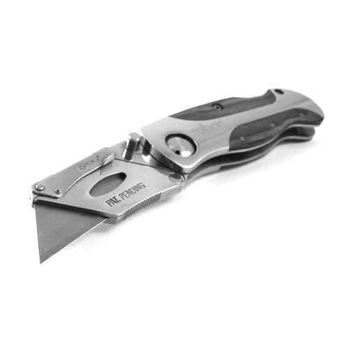
Utility Knife
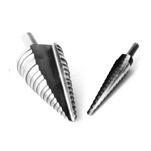
Step Drill Bit
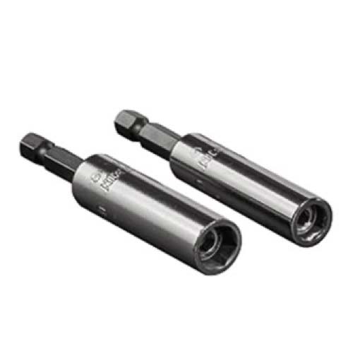
Nut Driver 5/16″ & 1/4″

Assorted 16 AGW Wire
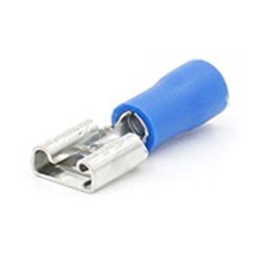
Blue Crimp

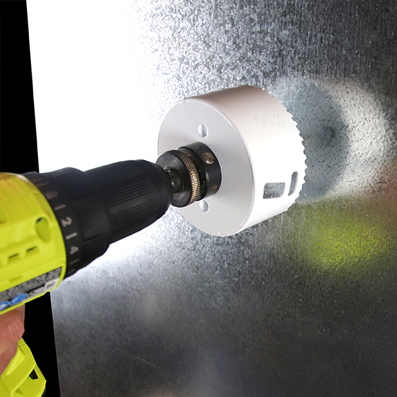
Power Drill

Tin Snips

Gloves
3-5/8” Knockout Punch
24 Volt Transformer

Crimpers
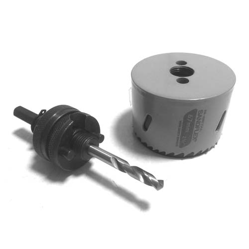
3 5/8″ Hole Saw

Protective Eye-Ware
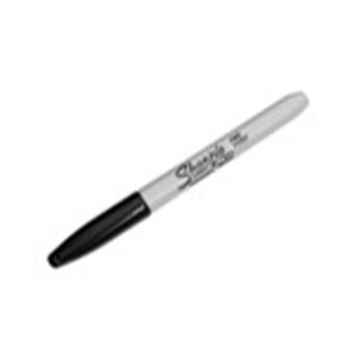
Sharpie
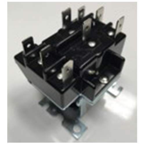
DPDT Relay
Installation Instructions
Here’s a Step -By -Step Guide to Install the C6 or C10 Phenomenal Aire Models

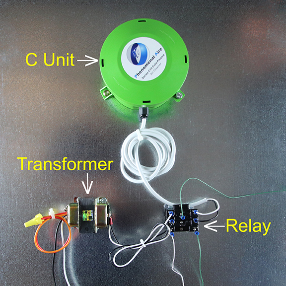
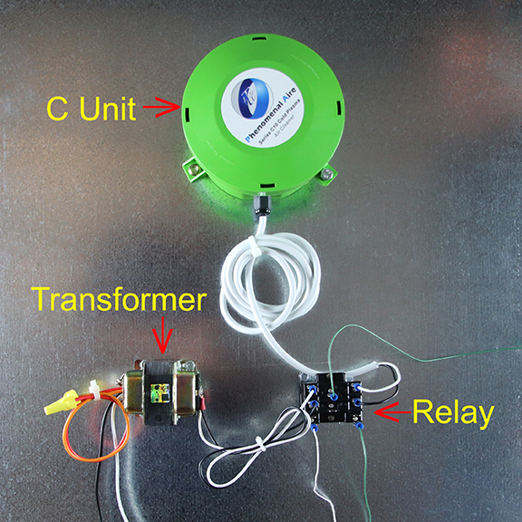
Completed Installation
C Unit Installation
When you have completed the installation of the Phenomenal Aire C6 or C10 Unit, it will look like the sample picture, unless the space available requires a different placement of parts.
Be sure to leave enough cord to the C Unit so that removal is easy.
Also, make sure that the location of the C Unit provides enough space for stingers to extend into the ductwork
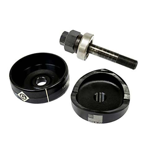
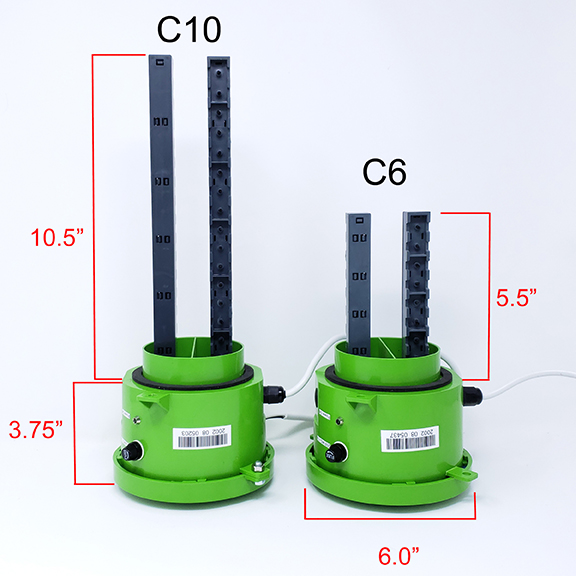
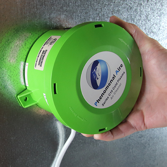
C6 or C10 Units
C Units
The Phenomenal Aire C6 and C10 Units are shown in the picture.
Again, be sure to leave enough cord to the C Unit so that installation and removal are easy.
Do not pick up the C Units by the Stingers. Be sure to pick up the C Units by the head cap.
Lockout/Tagout Safety Procedure
Lockout
Follow your company’s Lockout/Tagout safety procedure to ensure that the air handling unit and any electrical connections are properly deenergized prior to the beginning any installation.

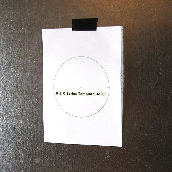
Step 1
3-5/8” Hole Template – Placement
Locate the best position for mounting the C Unit.
Tape the hole template ( found in the C Unit box.
Step 2
3-5/8” Template Pilot Hole
Drill a pilot hole for the 3-5/8” hole saw.

Step 3
Drill 3-5/8” Position Hole Saw Center Drill
Position the Hole Saw Center Drill to begin drilling the 3-5/8” hole.
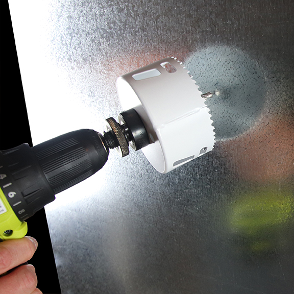
Step 4
Complete Drilling 3-5/8” Hole
Do not rush or try to push the hole saw because it will bend the sheet metal. Rather, take your time to keep the saw level as it removes pieces of sheet metal. The saw will eventually cut through the metal and the circular sheet metal will usually be found at the end of the hole saw. Be careful, the circular dish can be hot due to the friction produced in cutting the sheet metal.
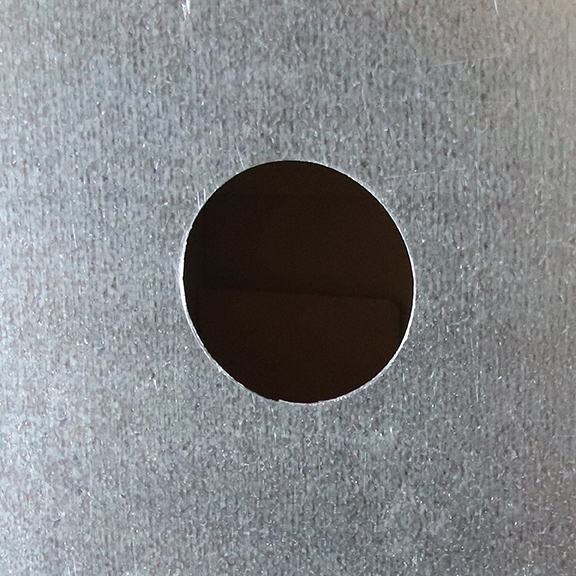
Step 5
3-5/8” Finished Hole
Remove any burrs or sharp edges around the hold.
Please note, the 3-5/8” hole can also be created using tin snips or a knockout punch.
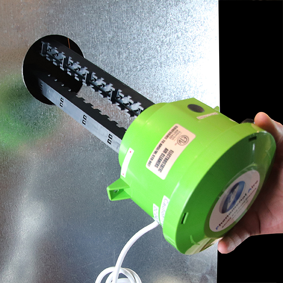
Step 6
Begin to Insert C Unit into 3-5/8” Hole
Carefully insert the C Unit into the 3-5/8” hole until it is flush with the panel.
Step 7
Fully Insert C Unit into 3-5/8” Hole & Position for Air Flow Direction
Carefully insert the C Unit into the 3-5/8” hole until it is flush with the panel.
Be sure that the air flow arrows align with the normal flow of air in the Air Handling Unit.
The Airflow Direction is printed on the label on the housing.
Step 8
Air Flow Alignment
Precisely align the Phenomenal Aire unit so the indicated arrows are in line with the air handling system’s air flow.
If you were inside the duct, you would see the stingers aligned as shown in the picture.
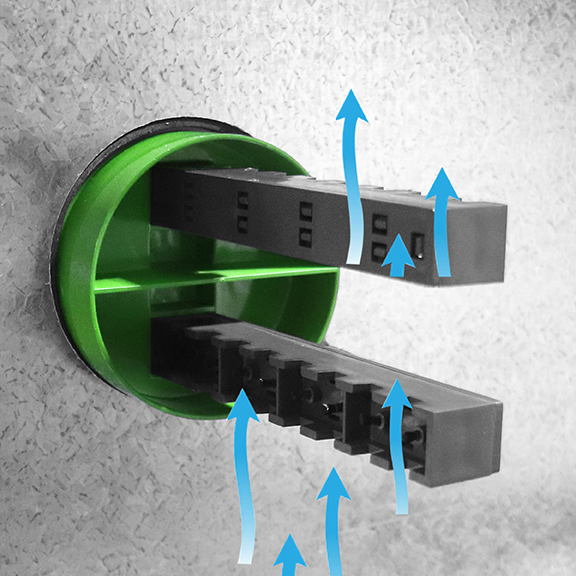
Step 9
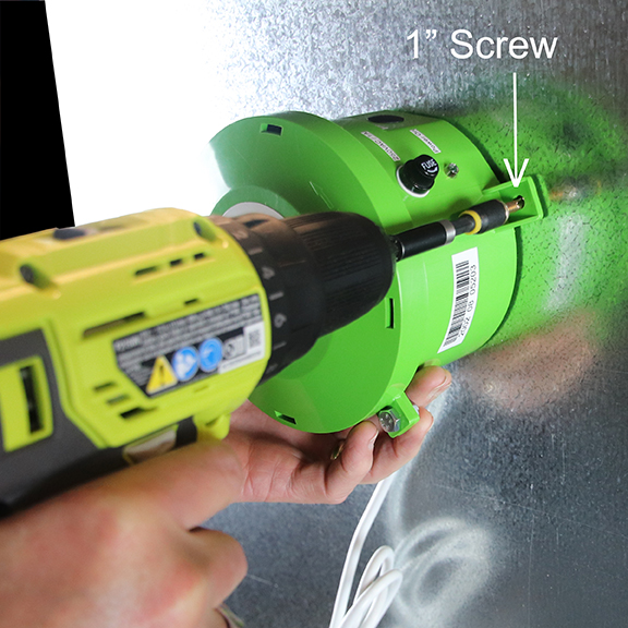
Secure the C Unit
Secure the C Unit to the panel with one #10 1” self-tappingsheet metal screw on the right side of the C Unit.
Make sure the unit is aligned in the proper air flow direction.
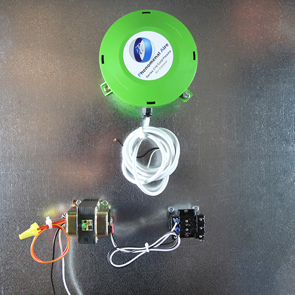
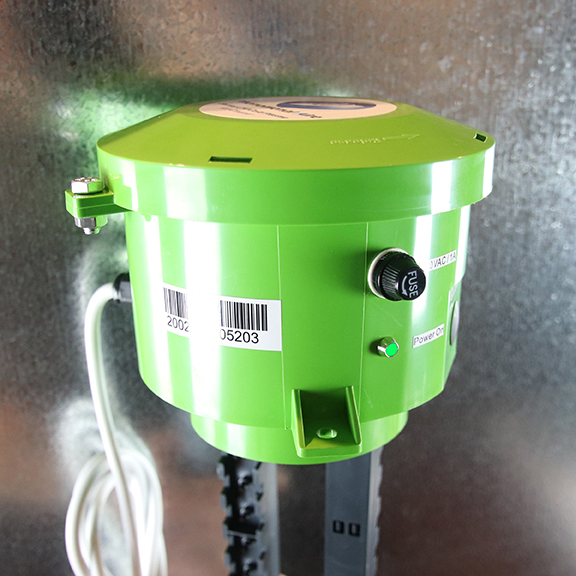
Installed C Unit
Installed C Unit Shown Ready for Wiring
This completes the C Unit mounting steps.

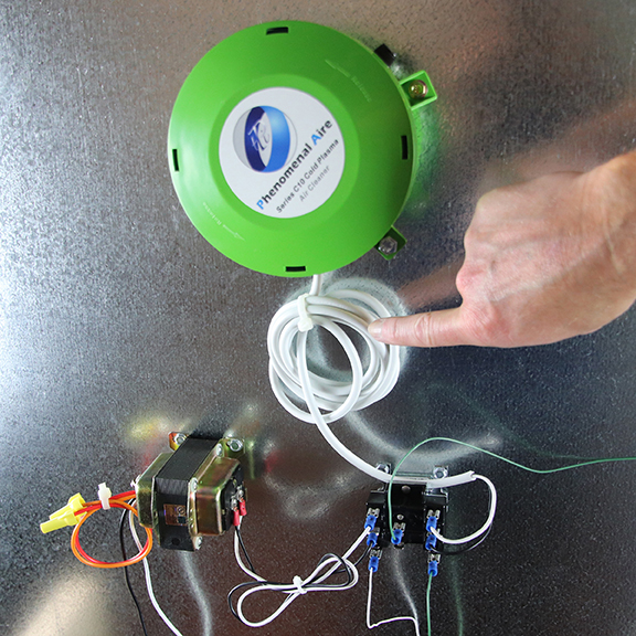
Step 10
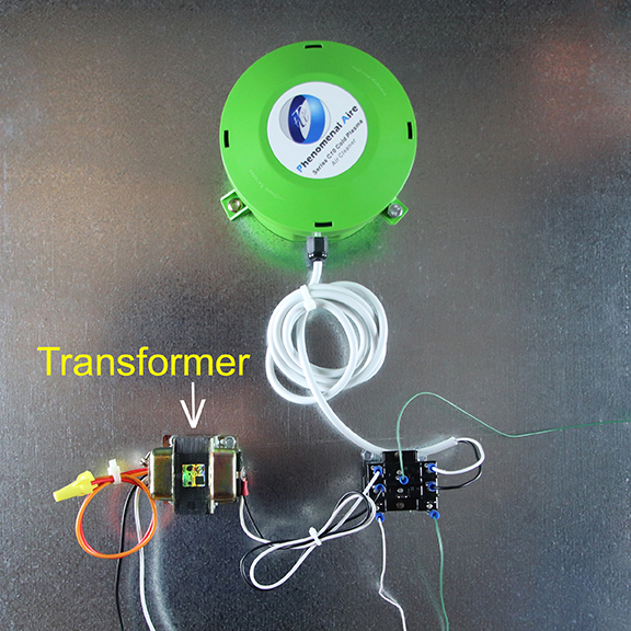
Transformer Installation
Remember when you have completed the installation of the Phenomenal Aire C Unit, it will look like the sample picture, unless the space available requires a different configuration.
Be sure to leave enough cord to the C Unit so that removal is easy.
Step 11
Position Transformer
Locate the transformer on the panel close to the C Unit.
We are using theHoneywell AT140A1018 -Foot Mounted 120/208/240 VacTransformer w/ 9 in. Lead Wires (40VA) to 24 Vac in this installation example
Please consult the manufacturer of your transformer for wiring instructions
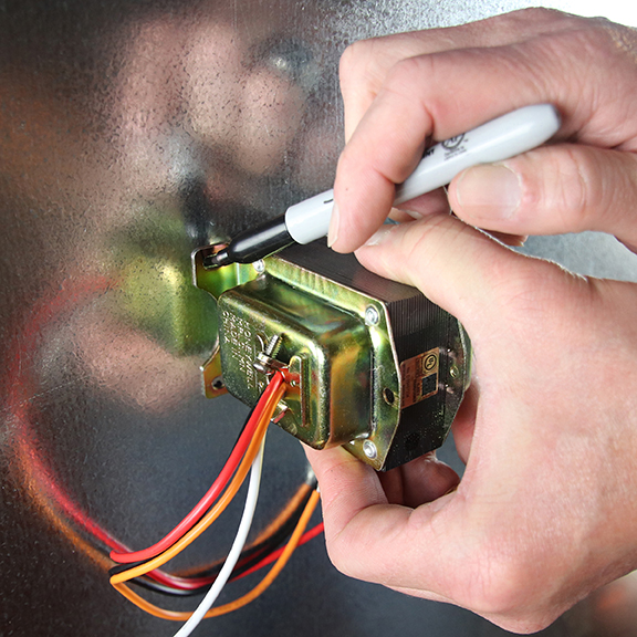
Step 12
Mark Transformer Mounting Holes
Mark the transformer mounting holes.
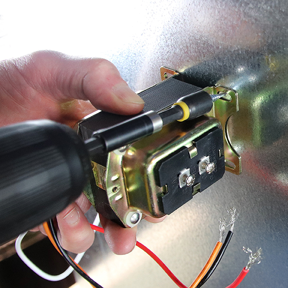
Step 13
Secure Transformer
Secure the transformer on the panel using self-tapping hex/slotted screw.
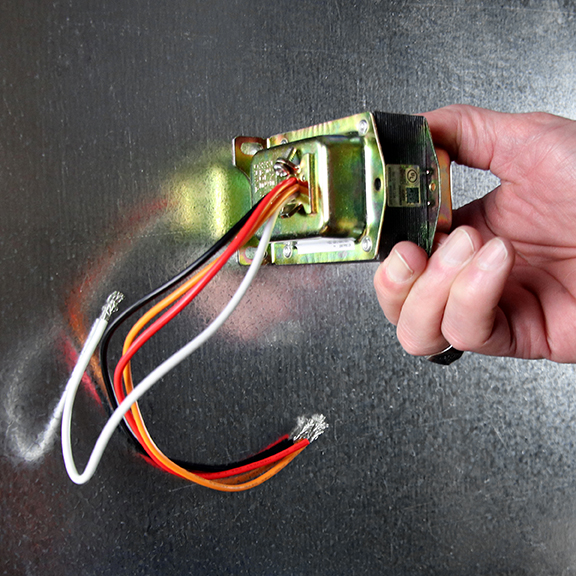
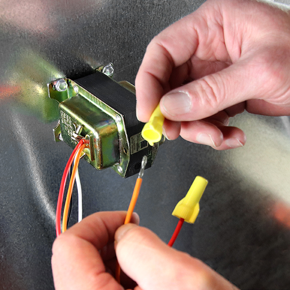
Step 14
Cap Transformer Wires Not Used
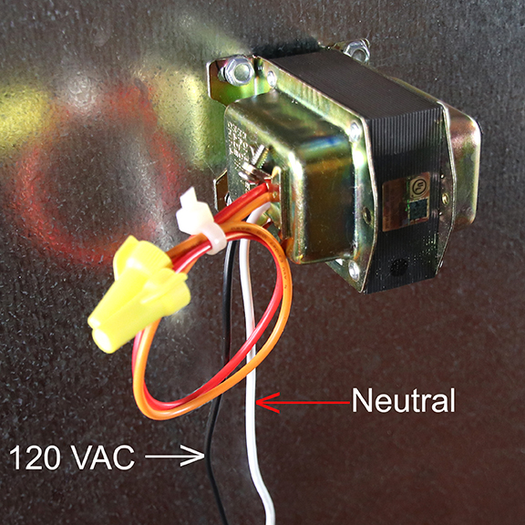
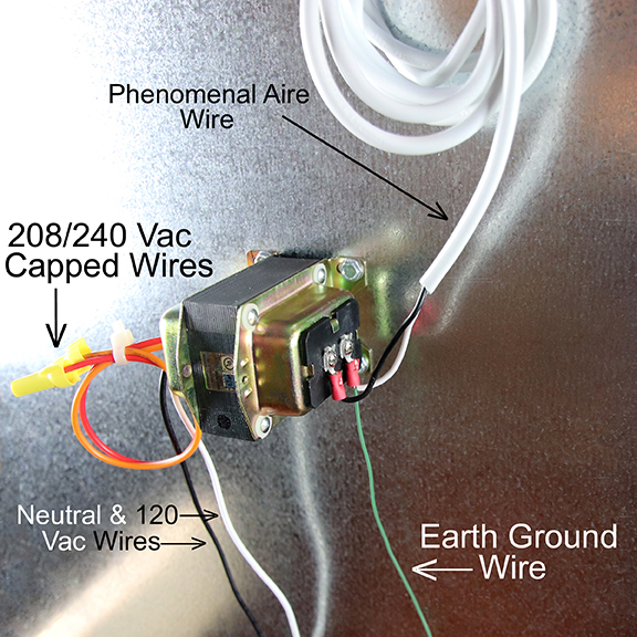
Cap the transformer wires not being used in the installation.
Typically, the red and orange wires are used for 208/240 Vac.
The black and white wires, used for 120 Vac, will be used in this sample installation.
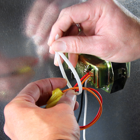
Step 15
Wire Tie Transformer Wires Not Used
Wire tie the capped transformer wires not being used in the installation.
Step 16
Connect Transformer to 120 Vac
Connect the white (neutral) and black (120 Vac) wires to voltage available in air handling unit.
Step 17
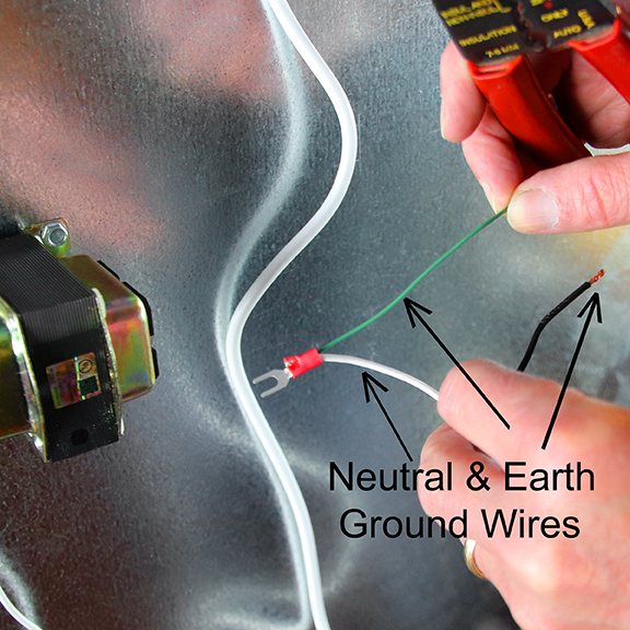
Strip C Unit Wires and Secure Fork Spade Lugs with Ground Wire
Strip the C Unit white (neutral) and black (120 Vac) wires.
You will need a length of green wire that will go to Earth ground.
Crimp a fork spade lug on the end of the black wire.
Crimp a fork spade lug on the end of the white wire along with a green wire that will go to Earth ground.
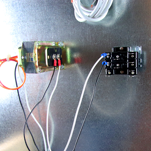
Step 18
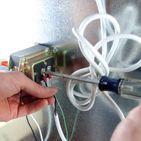
Secure Fork Spade Lugs to Transformer
Connect the white/green and black wires to transformer and tighten the transformer screws.
Step 19
C Unit Wiring Complete – If Relay Not Required
Carefully roll up the C Unit wire when finished, but be sure leave enough wire for the unit to be removed.
At this point you will be finished if you were able to tie the 120 Vac back to a source that is switched on and off with by the air handling unit.
If the transformer is tied to an unswitched 120 Vac source, you will need to use a relay to isolate the circuits, This is covered in the following Steps.
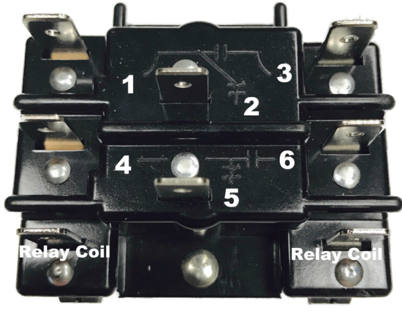
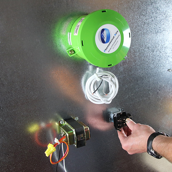
Step 20
DPDT Relay Operation
Position the relay. The relay shown is a 90-340. It is commonly used in the air handling industry. It is a double pole (DP) double throw (DT) semi-enclosed relay.
The 24 volt coil is energized through the bottom two terminals. Terminals #1 and #3 close the circuit at the top, and terminals #4 and #6 close at the bottom. These terminals would be called “NO” (Normally Open) because they are both normally open until the relay coil is activated.
Terminals #2 and #5 are available for connection to Earth Ground, you will be selectingone of these during the installation.
If you are interested in more detail you can look at the HVAC School https://www.hvacrschool.com/understanding-relays-90-340/
Step 21
Position Relay
Position the relay so the wiring is easy to follow, thereby reducing possible errors.
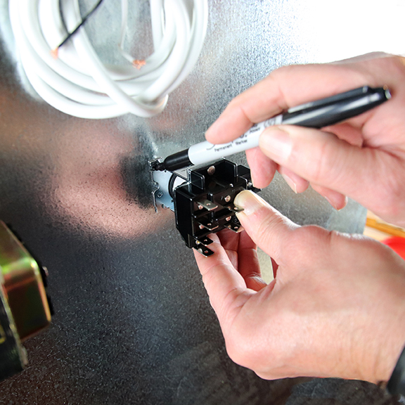
Step 22
Mark Relay Mounting Holes
Mark the mounting holes as shown.
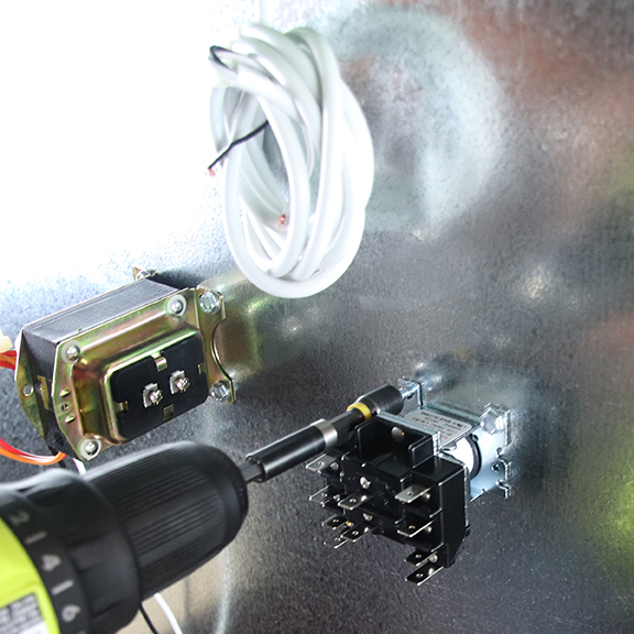
Step 23
Secure Relay with Self-tapping Screws
Secure the relay to the panel with sheet metal self-tapping screws.
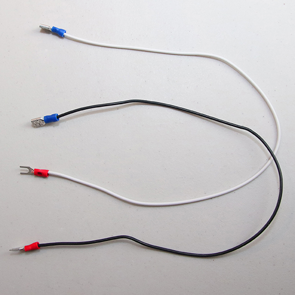
Step 24
Prepare Two Wires for Connecting the Transformer to the Relay
Cut a length of white and black wire each long enough to connect the transformer and the relay.
Crimp a fork spade lug on the end of the white wire and one on the end of the black wire.
Crimp a female spade lug on the other end of the white wire and one on the other end of the black wire.
Step 25
Connect the Two Wires between the Transformer and the Relay
Cut a length of white and black wire each long enough to connect the transformer and the relay.
Crimp a fork spade lug on the end of the white wire and one on the end of the black wire.
Crimp a female spade lug on the other end of the white wire and one on the other end of the black wire.
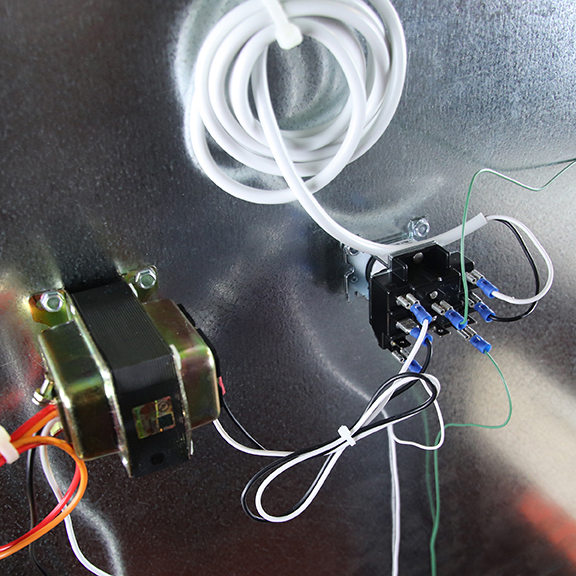
Step 26
Connect the Relay to Earth Ground
Crimp a female spade lug onto a green wire that goes to the Earth Ground.
Step 27
Connect the Relay to the Thermostat
The green wire shown in the picture connects to the thermostat panel.

Step 28
Connect the Relay to the Thermostat
Crimp a female spade lug onto a white wire that goes to the thermostat panel.
Please note: there isn’t an official standard for thermostat circuit wiring colors, but there is a general pattern.
It is best to look at the manufacturer’s documentation (both thermostat and HVAC).
You may need to find the 24 Vac connections from the manufacturer’s manual.
Step 29
Connect the Relay to Earth Ground
Crimp a female spade lug onto a green wire that goes to the Earth Ground.

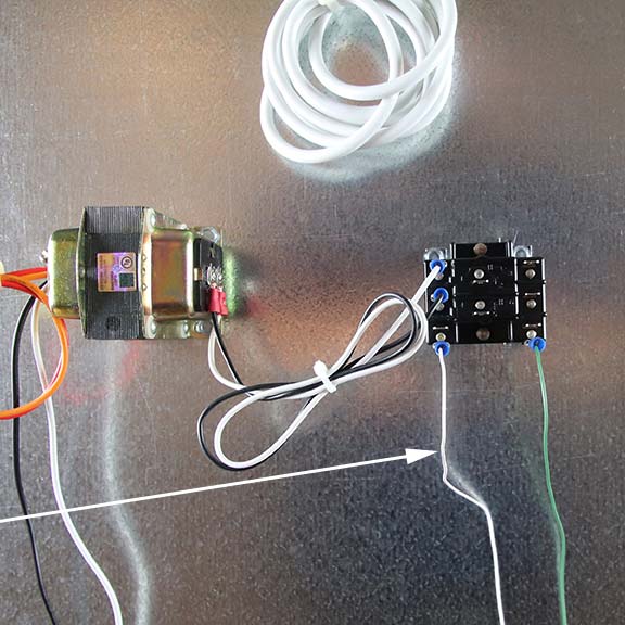
Step 30
Connect the C Unit to the Relay
Crimp a female spade lug onto the C Unit white wire and one onto the C Unit black wire.
Attach the female spade lugs to the relay terminals that correspond to the transformer wires (white to white and black to black).
As shown, the white wire on terminal #1 will connect with the white wire on terminal #3, and the black wire at terminal #4 will connect to the black wire on terminal #6.
Step 31
Coil and Wire Tie the C Unit Wire
When you are finished, please be sure to coil the C Unit wire and wire tie it so it does not get in the way of others who will need to access the air handling unit.
Step 32
Check that the C Unit is Working
After installation has been completed, remove the Lock-out/Tag-out from the power box and turn on the air handling system.
The green LED, located below the fuse, should come on to indicate that the C Unit is energized.
Step 33
Installation Complete – Check List Item
If the C Unit needs to be connected to the building management system (BMS) continue to the next slide.
Step 34
Access the Connection Block for the Building Management System
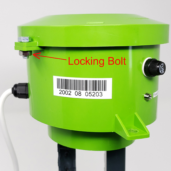
Remove the C Unit from the air handling panel.
Remove the locking bolt to inspect and wire the connection to the building management system.
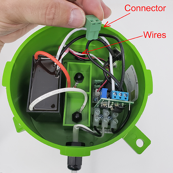
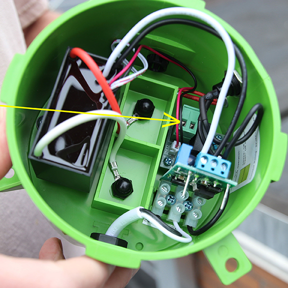
Step 35
Access the Connection Block for the Building Management System
To connect to the Building Management System (BAS), remove the plug-in terminal block and connect the wiring as instructed by BAS.
Step 36
Optional connections of Building Automation System (BAS) dry contact connector
Remove connector & install wiring for dry contact to building management system through pre-drilled hole using the supplied wire grommet.